The early laying machine was a vertical looper, and the wire rod entered the looper and formed a circle downward, and was scattered on the air-cooled roller table. The working speed of the looper is relatively slow, and can only meet the needs of wire rod rolling with a rolling speed below 30m/s. Due to the continuous increase of rolling speed, the old-fashioned looper can no longer meet the requirements of higher rolling speed, so the horizontal laying machine came into being. The inclination angle of the horizontal laying head is 5 or 10° at the earliest. The mainstream horizontal laying heads include Morgan, Danieli, Demark, SMS, Ashilo, Pomini and other models, and the design speed is also from the earliest. 40m/s jumped to the current 140m/s. With the acceleration of the rolling speed, the inclination of the laying machine is also increasing, from the initial 5° and 10° to the current 15° and 20°. The downward inclination angle of the horizontal laying head is to ensure the transition between the laying head and the air-cooled roller table. The working spindle of the laying head is equipped with a laying tube in the shape of a spatial spiral curve, and the laying tube rotates at a high speed with the main shaft of the laying head. The wire enters the inside of the laying machine and enters the laying tube. The frictional resistance of the inner wall of the laying tube reduces the speed and bends it into a circle. The spinning tube is spit out along the tangential direction of the circumference to form a coil, and the spinning disc will form a circle. the wire is pushed forward.
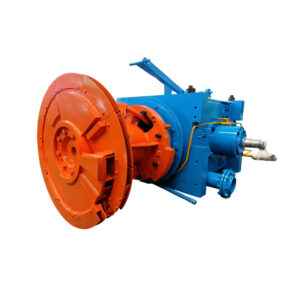
The laying machine is composed of a transmission gear, a hollow shaft, a laying cone, a laying tube, a laying disc and a bearing housing box. It relies on a spiral bevel gear for vertical transmission, which is generally a single-stage speed-increasing or constant-speed gear. The motor rotates through a gear-driven hollow shaft, and the speed of rotation depends on the rolling speed. The axial direction of the input shaft is perpendicular to the rolling line, and the axial direction of the output shaft is the same as the rolling line. The input shaft of the laying machine is driven by gears, and the output shaft gear is located between the two bearings, but the front end of the hollow shaft of the laying machine is connected with a larger quality tap, and the cantilever is supported outside the laying box. The structure of the laying head and its high working speed put forward higher requirements for the manufacturing and assembly accuracy of the laying head equipment parts, as well as the dynamic balance adjustment accuracy. At present, the dynamic balance of the rotor and the whole machine of the laying machine requires an accuracy grade of ISO standard G13.4, and the counterweight method is to add counterweight blocks to the two planes on the laying head.
The hollow shaft of the laying head is generally axially positioned by two disc angular contact ball bearings, the floating end is supported by a disc cylindrical roller bearing to support radial force, and the transmission gear is located on the hollow shaft near the end of the axial positioning bearing. The purpose of this design is to minimize the change of gear clearance caused by the expansion of the hollow shaft due to heat during operation, thereby affecting the transmission effect.
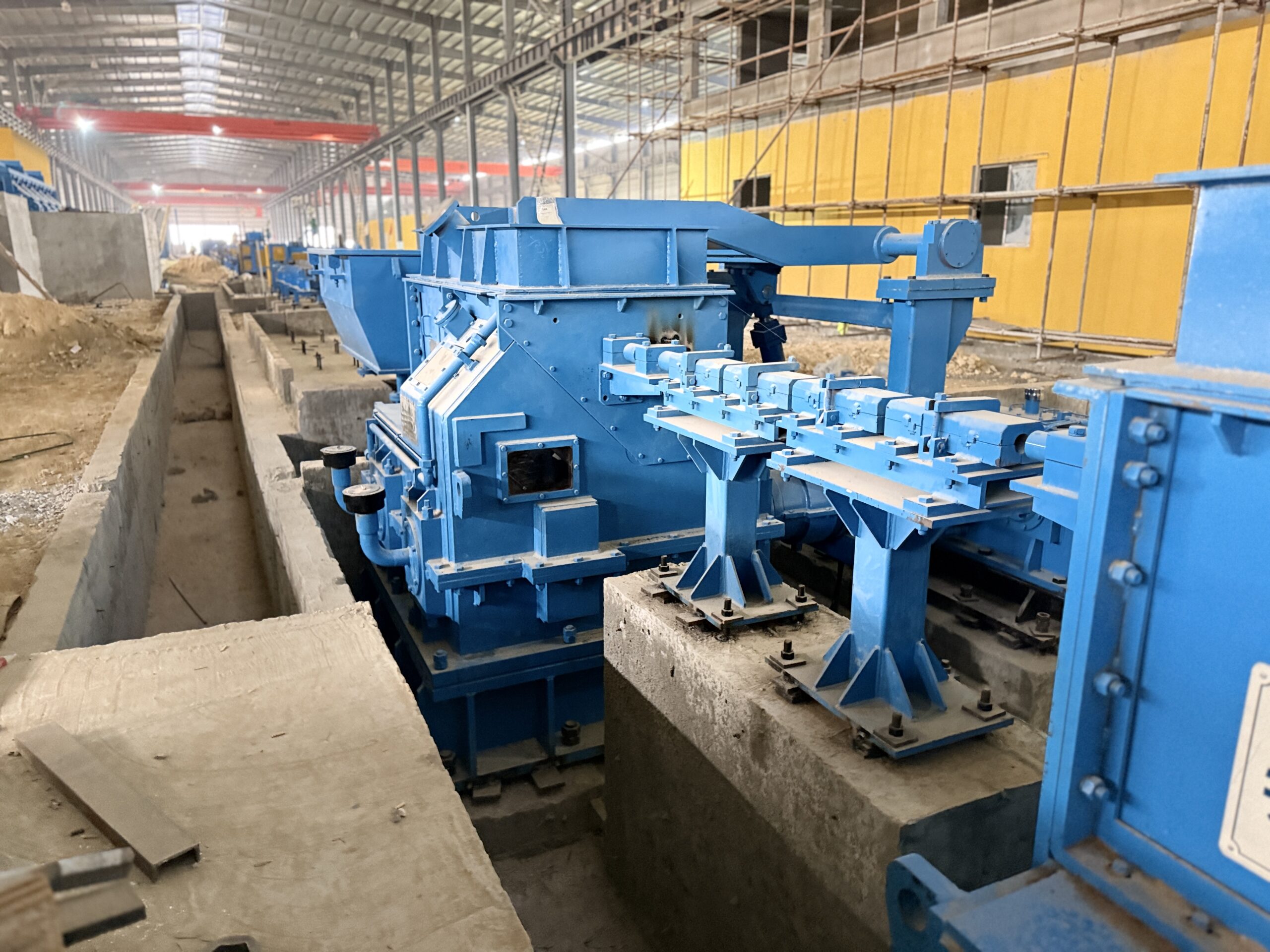
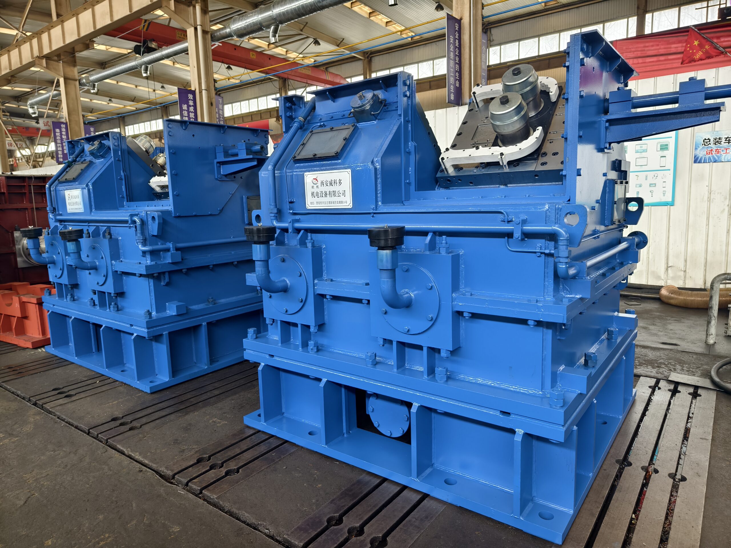
At present, our company’s laying machines are mainly divided into 5 models, namely 90-meter laying machine, 135-meter laying machine, 140-meter laying machine, Morgan six-generation laying machine and oil film bearing laying machine.