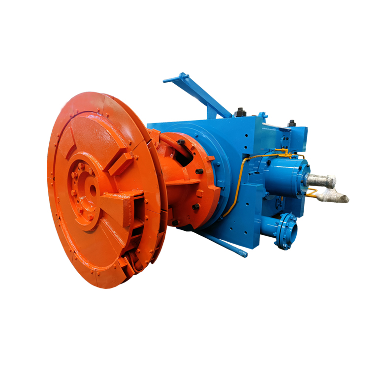
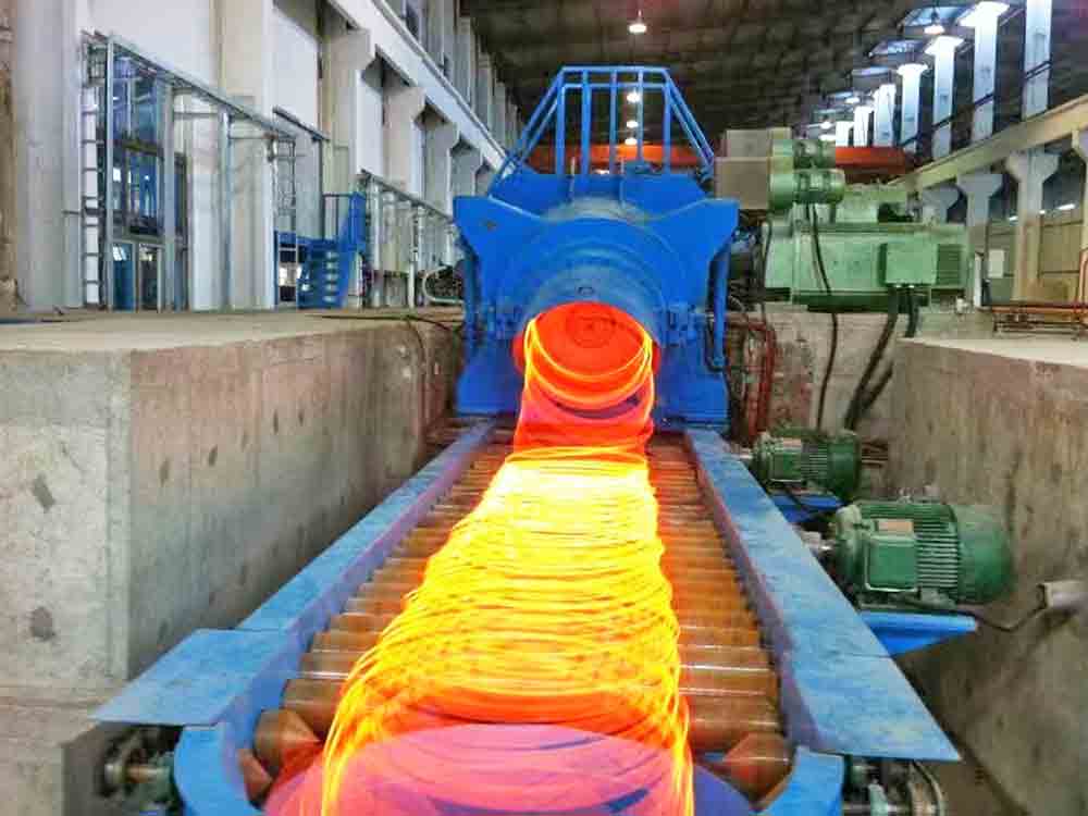
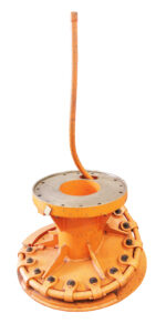
The Transmission Gear Box Of The Spinning Machine Is Of Welded Structure, The Gears And Bearings In The Box Are Lubricated With Thin Oil, And The Spinning Head Is Covered In The Safety Cover Of The Spinning Machine. The Reeling Machine And The Reeling Head Are Arranged Horizontally, And The Center Line Is Inclined Downward By 10 °, Behind The Water Cooling Device And Pinch Roller Of The Finishing Mill. The Reeling Machine Converts The Rolled Material Sent By The Pinch Roller Into A Spiral Coil With A Diameter Of 1080mm In A Circular Motion, And Lays It On The Unwinding Cooling Track (Subsequent Equipment) And Falls Into The Unwinding Cooling Conveyor.
Model
Speed of wire rod
m/s
Output wire diameter
Фmm
Motor power
DC KW
Steel grade
84m/s laying head
35-80
5.5-14
75-160
Low and medium carbon structural steels Low alloy steel
90m/s laying head
40-90
5.5-16
90-200
135m/s laying head
60-110
5.5-18
120-220
140m/s laying head
80-120
5.5-20
160-220
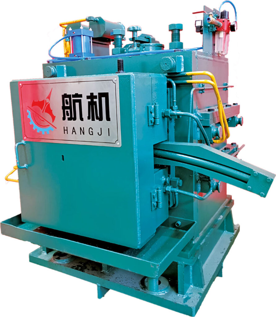
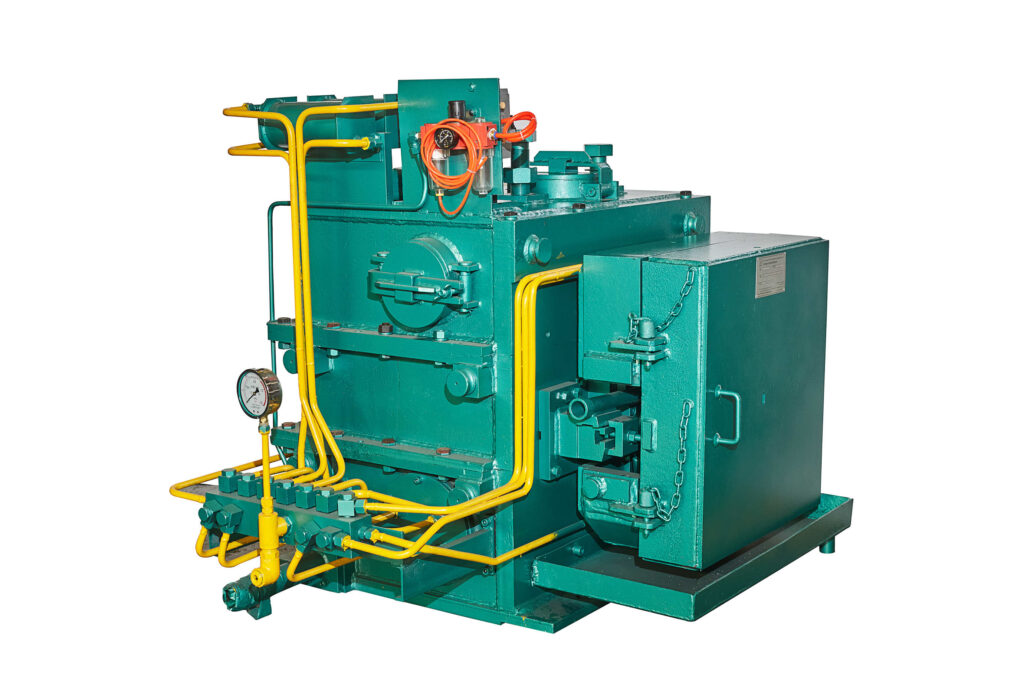
The pinch roller is a horizontal cantilever roller structure. It is driven by double rollers. The upper and lower rollers are clamped by the air cylinder at the same time. The gears and bearings are lubricated with thin oil. The pinch roll is arranged at the inlet of the spinner after the water cooling device of the finishing mill. According to the process requirements, the wire rod is clamped at the head, tail or whole process and the rolled piece is sent into the spinner.